Initial Front End Alignment – 1966 VW Beetle Project

Today I did the initial alignment (basically just the toe-in) on the new front end. I say “initial” because I plan to take it to a local vintage vw shop to have it done professionally too (I highly recommend it). I want it to be fairly straight/solid before I drive the car over to their shop though. With the tools that I have, I think I did a pretty good job. After performing the procedure below (in addition to what I did in my previous post), it certainly drives straight without any issues at all it seems.

I also highly recommend getting a Bentley manual for your year Bug to help with this procedure. There is a lot of good information in there, and some information may be specific to your year bug. Here’s an excerpt from the Bentley manual that I think is important:

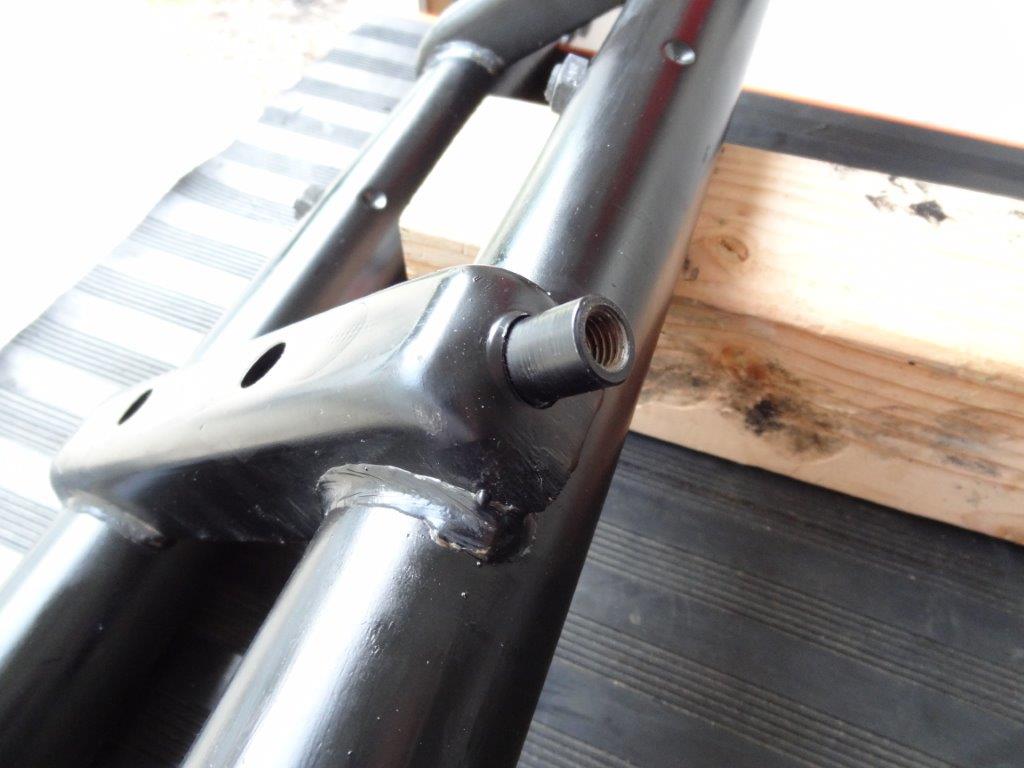
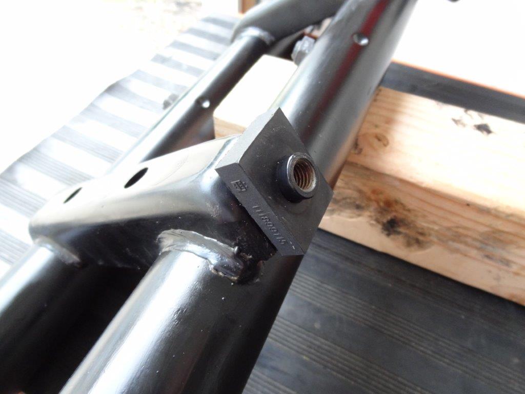
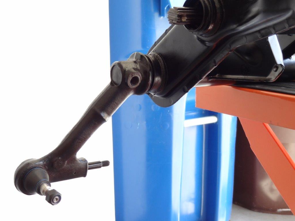
“Toe is adjusted by lengthening or shortening the tie rods. When tie rods are located behind the front axle (as on the VW), lengthening them increases toe-in. During this adjustment procedure, the steering must remain in the center position, as set by the marking ring on the worm spindle. If center position is disturbed in adjustment of toe-in, it must be re-set. To keep steering centered while toe adjustment is made, you must be careful to lengthen or shorten both tie rods by same amount”

The left ends of both the long and short tie-rods have left-hand threads. Therefore, lengthen rods by turning adjusting sleeves (or tubes) toward front of car. Shorten rods by turning sleeves toward rear of car.”

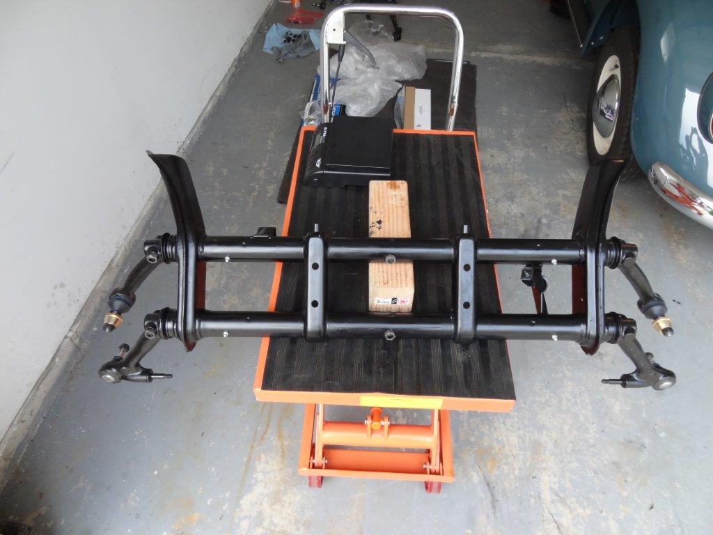
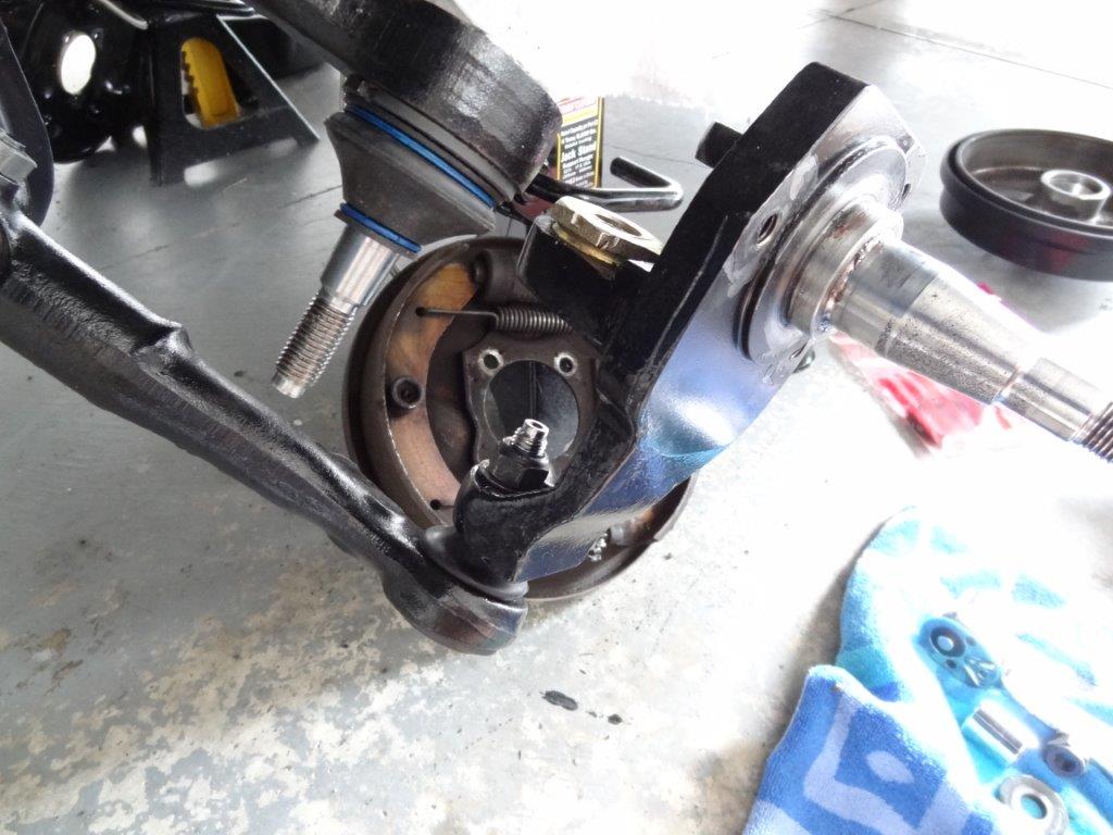
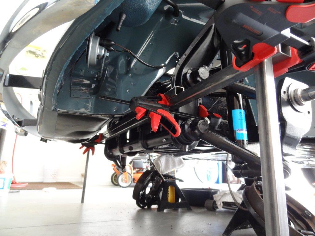
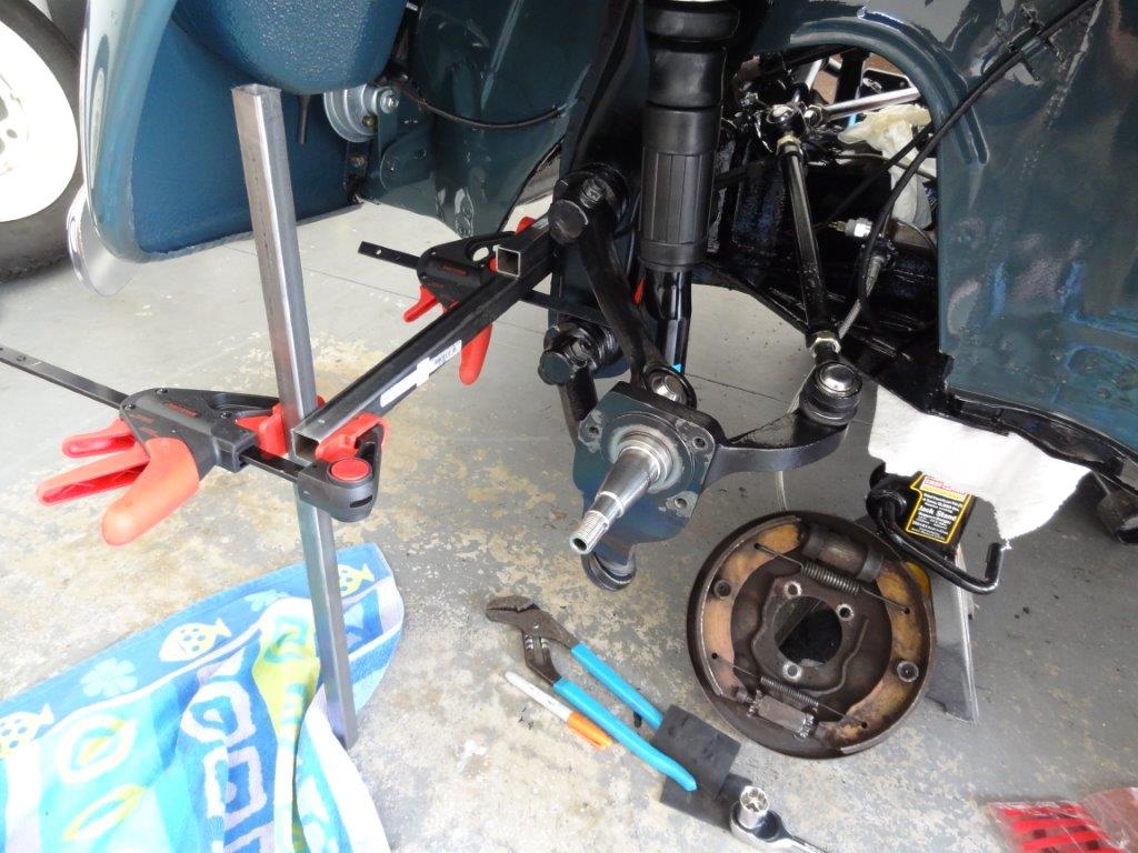
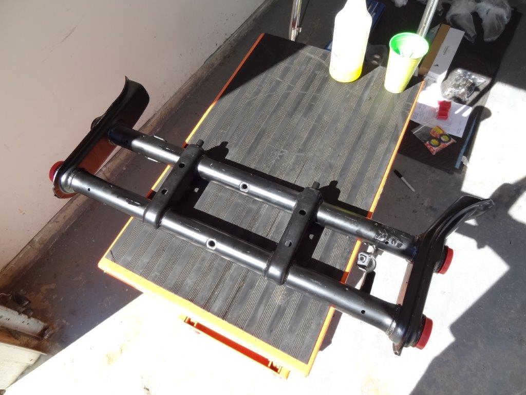
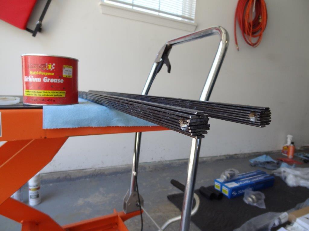
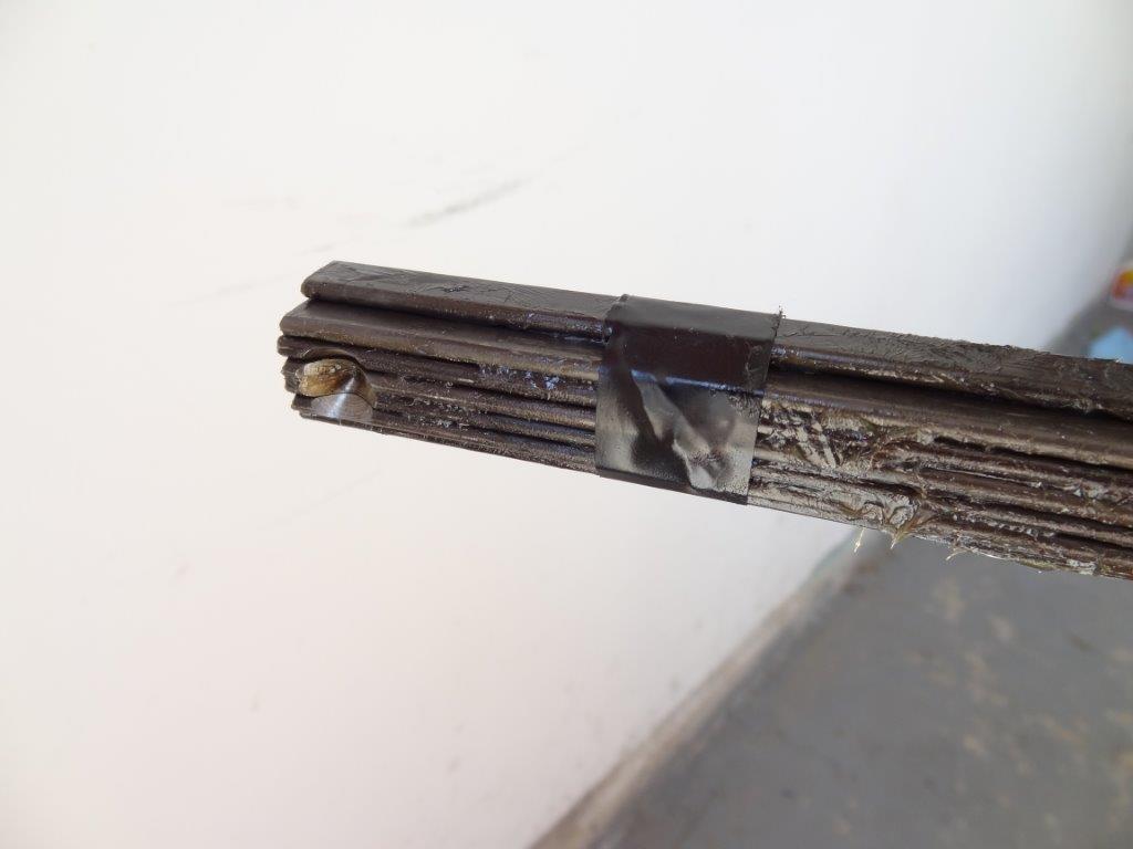
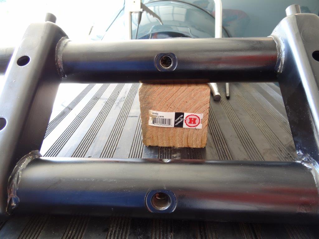
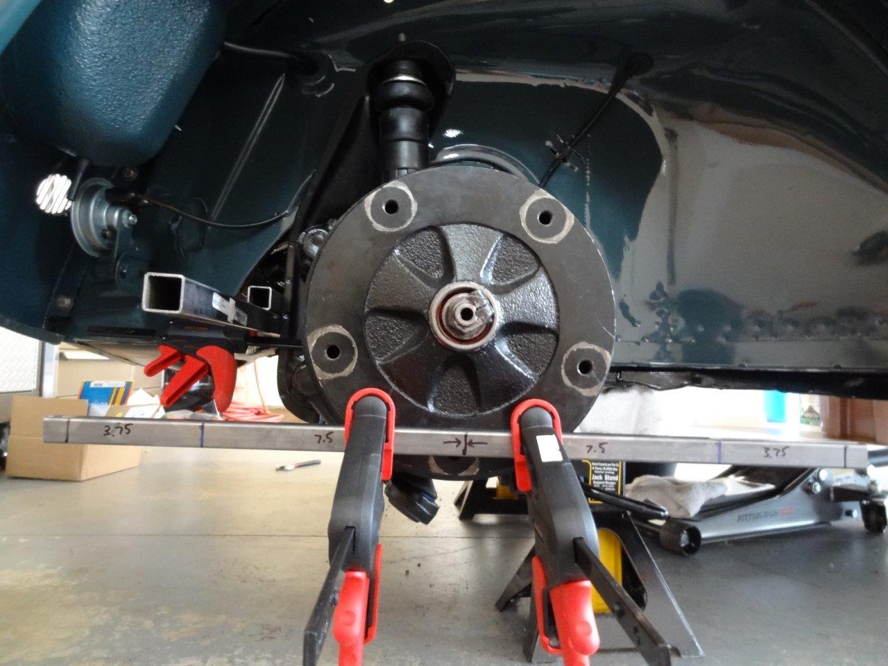
The first thing I did was take a couple of the square pipes from my last blog post and mark the distances of my 15″ wheels and tire height on them. I then clamped the square pipes to each front drum, as shown below. I lined up my center mark on the square pipe with the center of the spindle.

Driver Side:

DSC07858

Passenger Side:

DSC07856

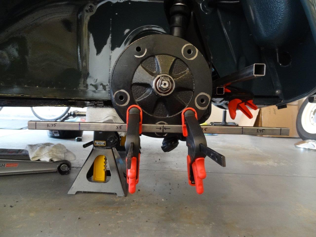
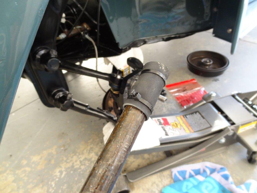
Once I had the square pipes into position, I then took some measurements using a tape measure. I measured from the point on the square pipe where the tire tread would be (the outer lines on the pipe) on the front of the tire and the back of the tire.

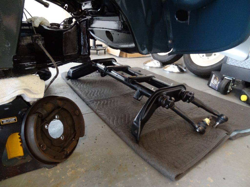
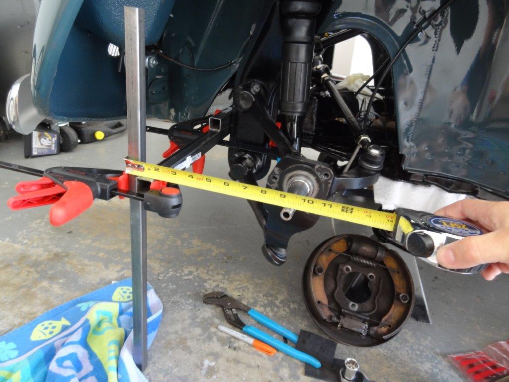
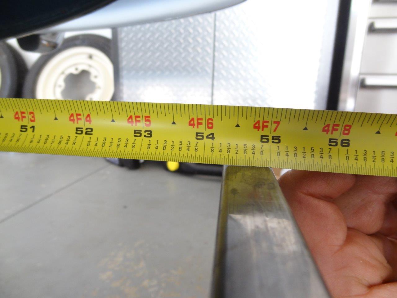
Here’s a wide shot of me measuring the back side (toward back of car) of the tires (I did the same measurement on the front side of the wheel at the same marking on the square pipe):

DSC07866

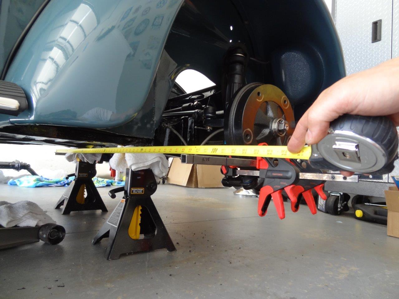
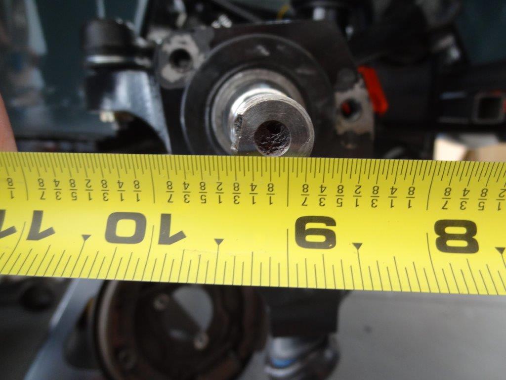
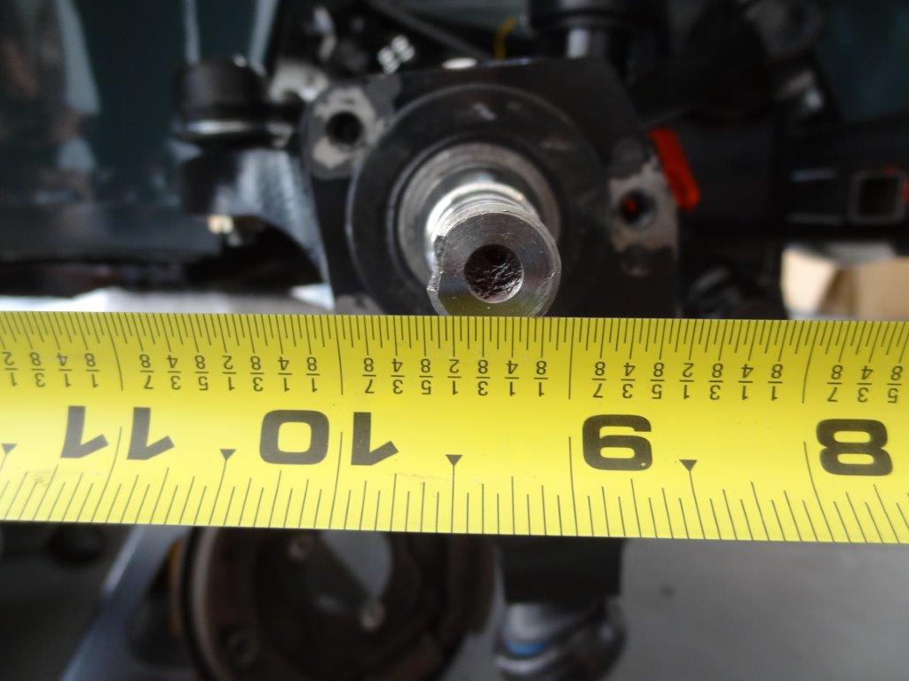
Here’s a close-up shot of that reading (Distance: 56-13/16 inches):

DSC07869

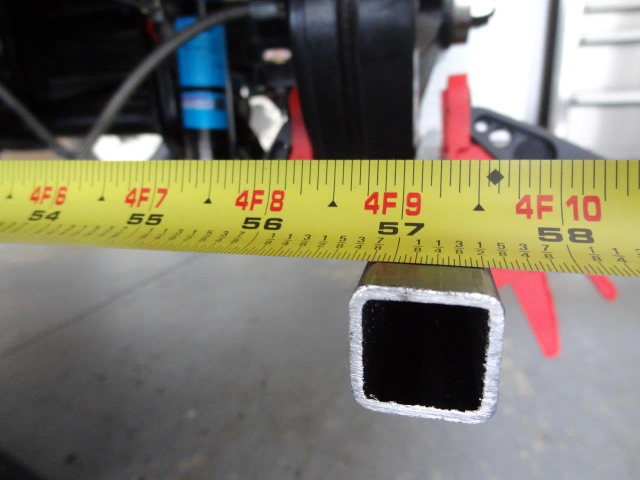
Here’s a close-up shot of the front measurement (Distance: 54-5/16 inches):

DSC07863

As you can see, the distances were off by over 2 inches. Since the front distance is the shorter distance, I had too much toe-in. Here’s a picture of my notes from today:

photo

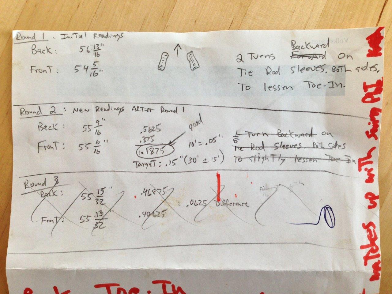
I needed to lessen the toe-in pretty considerably (I guess I should have matched the driver side spindle to the passenger side spindle in my previous post instead of the other way around. 😉 ). I turned the driver and passenger side tie-rod sleeves 2 full turns backward (toward rear of car) to decrease the amount of toe-in. Remember, turning them backward will shorten the tie-rods.

DSC07876

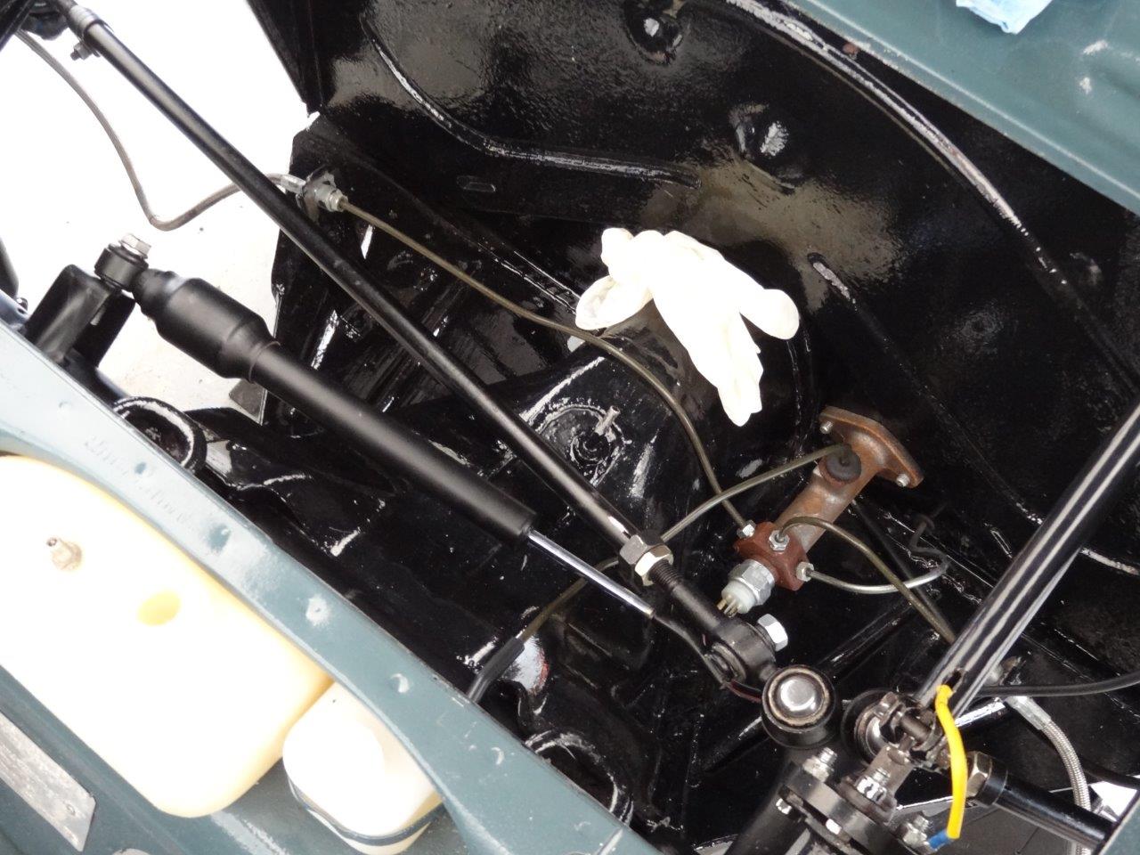
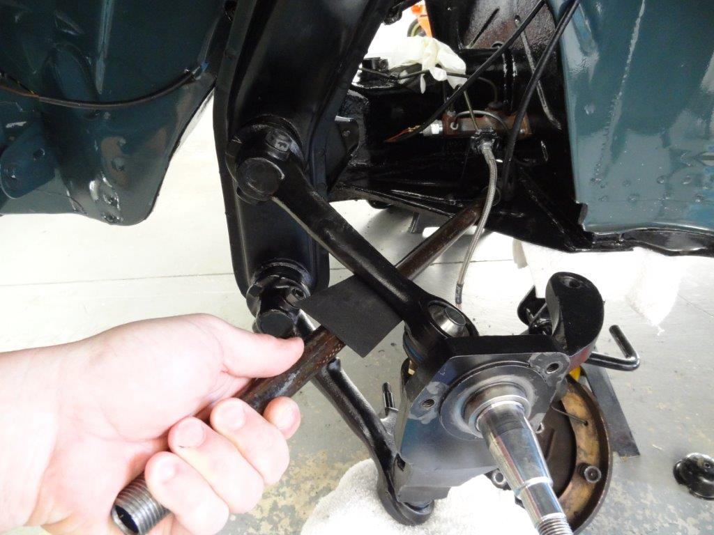
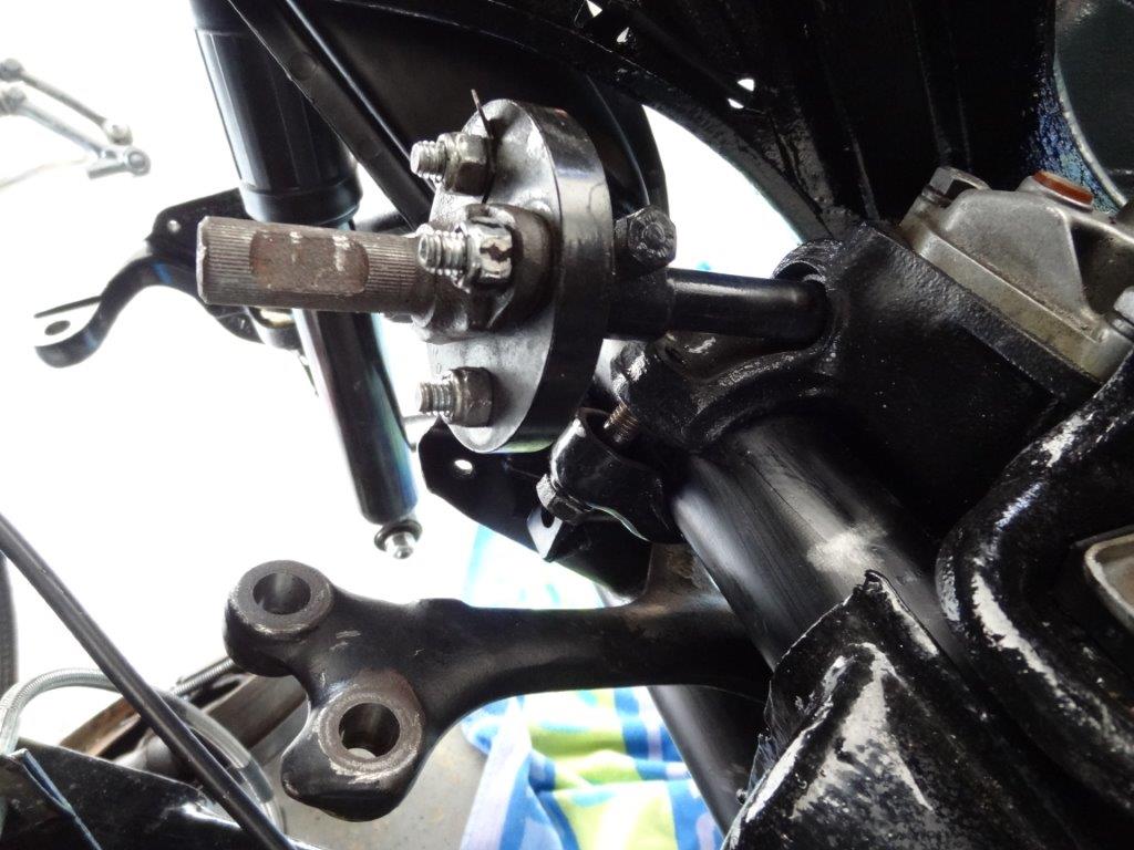
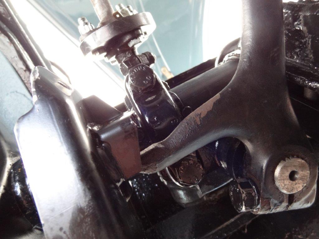
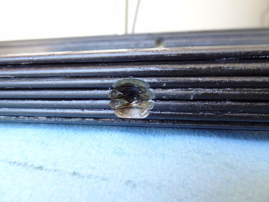
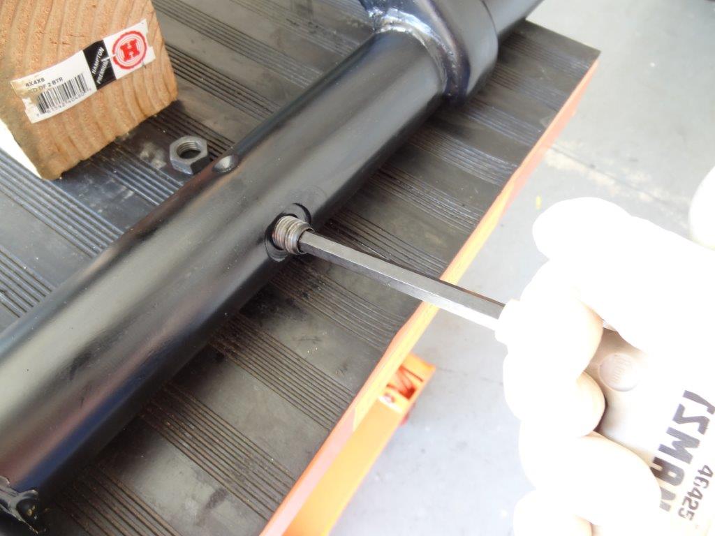
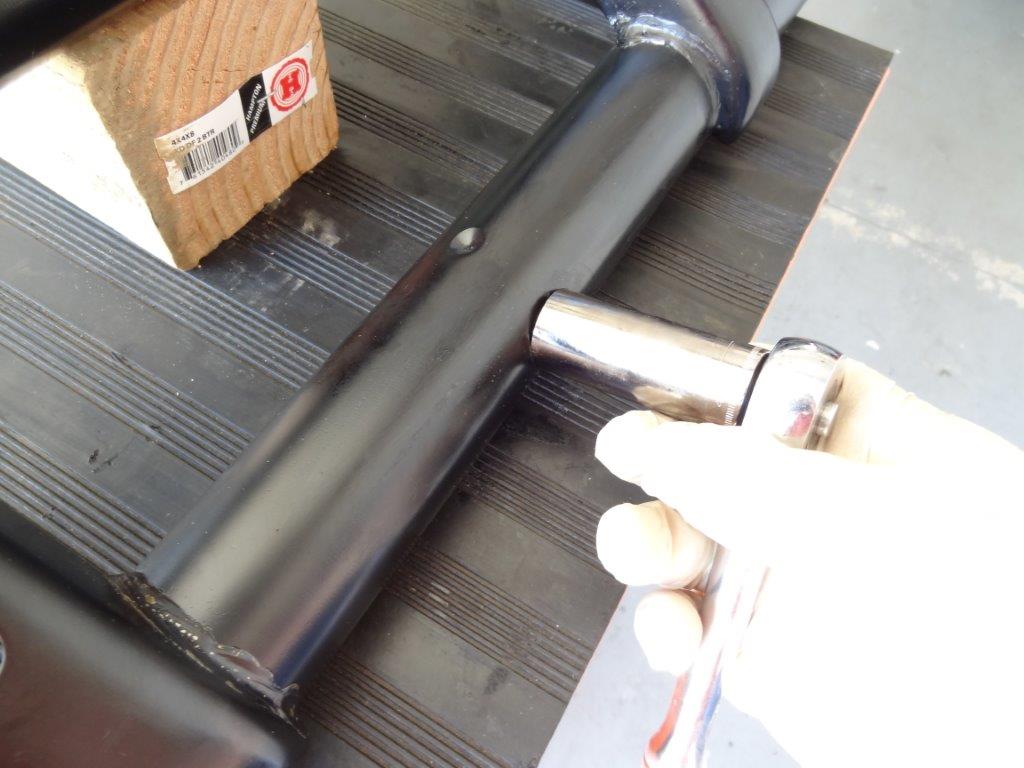
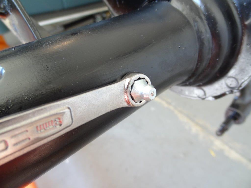
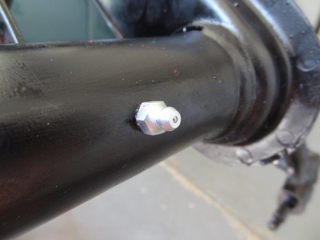
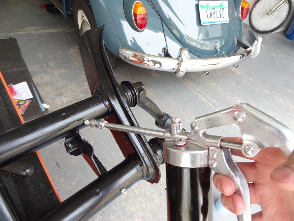
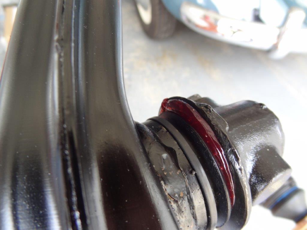
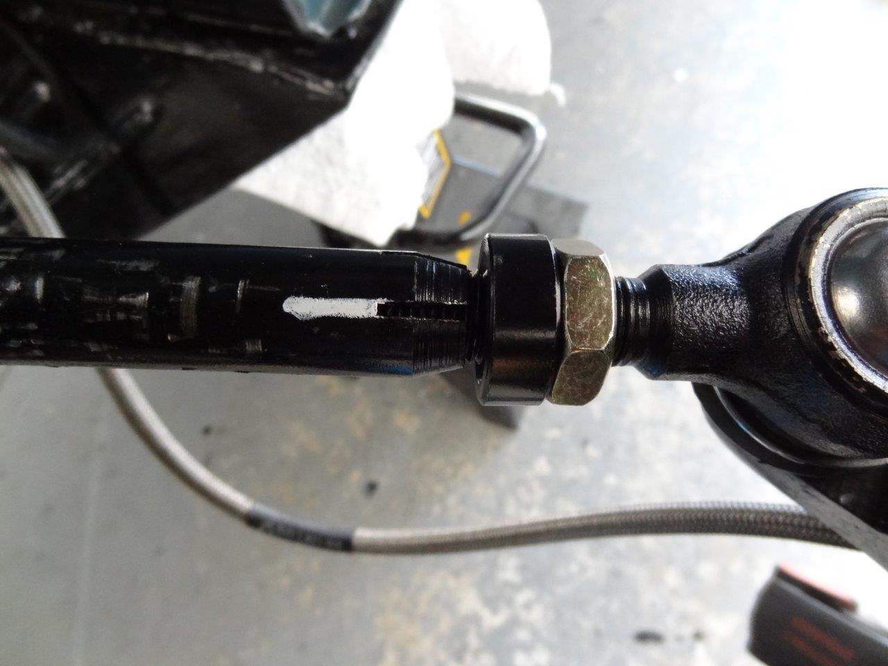
I made a white mark on each tie-rod so I could easily see how many times I spun them.

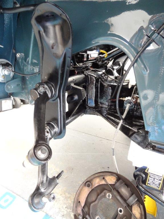
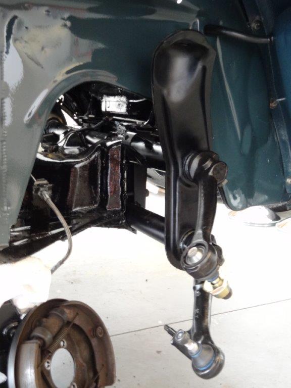
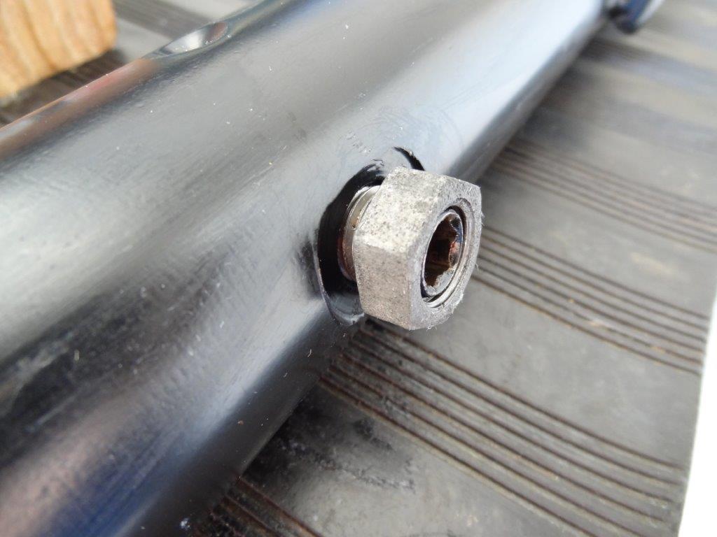
Here is the white mark on the passenger side tie-rod:

DSC07871

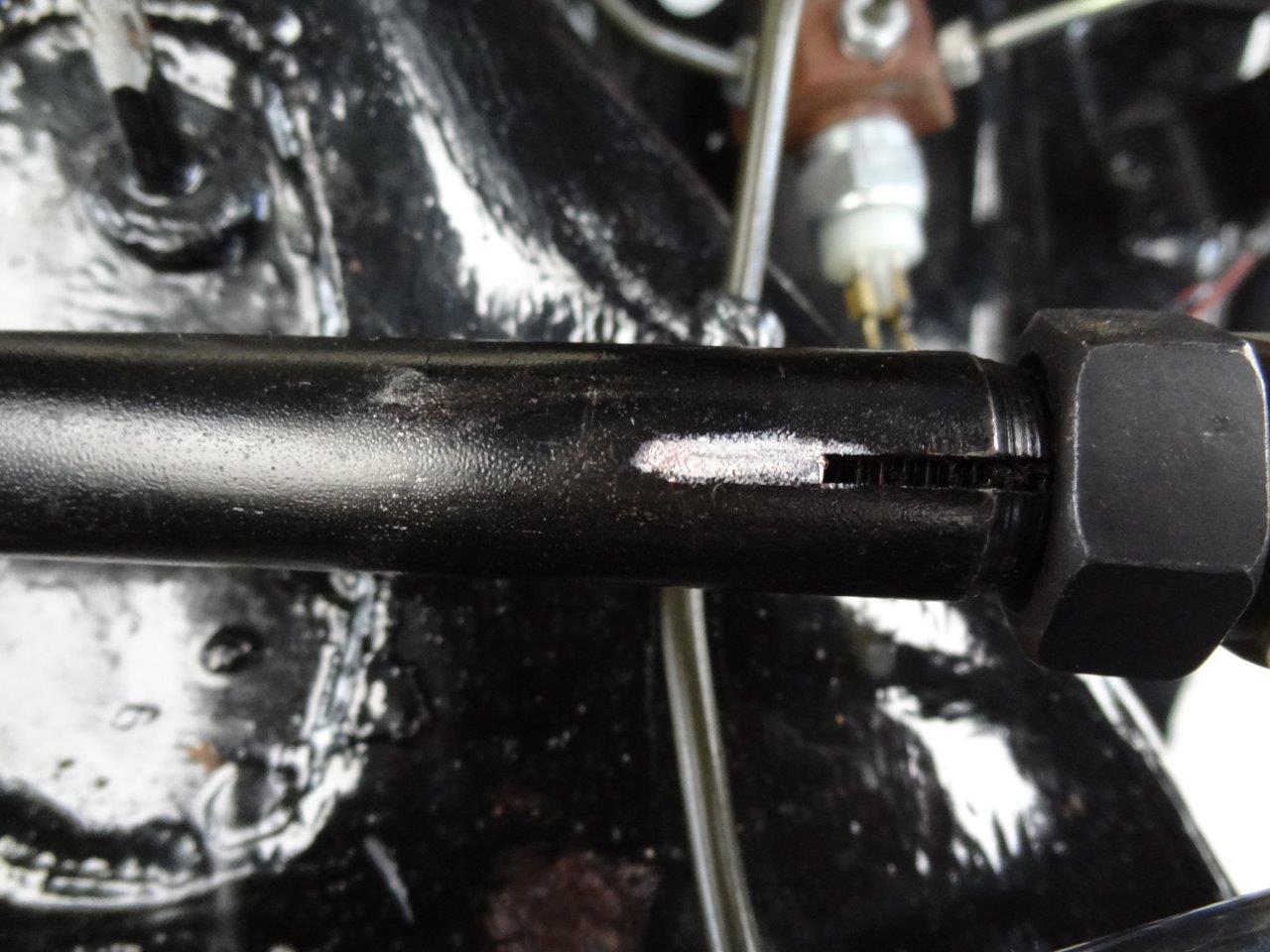
Here is the white mark on the driver side tie-rod:

DSC07872

My new measurements, after spinning the tie-rods 2 full turns, were:

Front Side Of Tire: 55-6/16″
Back Side Of Tire: 55-9/16″
Difference: 3/16″ (shorter on front)

According to the Bentley Book, the total toe-in (for 15″ wheels) without pressure on the wheels should be +30′ +- 15′. 10 angular minutes equals .05″ (10’=.05″). As you can see, the difference is 3/16″ (.1875″) which falls within the spec of (+30′ +- 15′). I hit .1875″ with my first adjustment.

I hope I described that pretty well. If nothing else, it will give you a very basic understanding of how to get yourself going somewhat straight down the road before driving your v-dub down to the local shop for a professional alignment. I HIGHLY recommend having a professional do it. I will, even though I feel the car is driving really well with just my adjustments as described above. A professional shop will set your wheel camber and caster as well, if needed. (I just realized I didn’t describe setting my camber in my previous post. I should have done that.)

Installing Stock Front Beam – 1966 VW Beetle Project

Now that my beam is complete (click here to read about that), it’s time to install it to the car. I’m lacking some good pictures in parts of this post. Sorry!

DSC07796

First thing, lets get the rubber body pad placed on the beam. This will be sandwiched between the beam and body, once the beam is installed in the car.

Before:

DSC07798

After:

DSC07799

Place the beam into position under the car…

DSC07800

Lift it up into place with a jack and tighten the 4 bolts that hold it to the framehead. Also, tighten the two body bolts that attach from above.

DSC07801

Here it is, installed…

DSC07809

DSC07807

DSC07806

Now that it’s installed, it’s time to install the spindles on to the trailing arms. I’m using the 2.5″ dropped spindles that I removed from the old narrowed beam. I think the 2.5″ drop will still give me a nice look, while maintaining the original VW stock steering/suspension geometry. This first picture shows the spindle installed on the bottom trailing arm. That’s the easy one to install.

DSC07810

The upper trailing arm is harder to install, and you’ll want to make a tool to help give you some leverage. I used a steel pipe with some lifter channel rubber padding wrapped around the end (don’t want to scratch the nice paint on the chassis). In the picture below, you can see how I used the pipe to help me lift the upper trailing arm into place on the spindle. Also, you can see that I have a jack (under the white towel) that lifted the bottom trailing arm up a bit for a better angle when inserting the upper trailing arm.

DSC07820

Below shows the lifter channel rubber wrapped around the end of the pipe. You can see in the image above that I also put a layer of the lifter channel rubber between the pipe and the upper trailing arm. Again, it protected the paint and in this case provided some grip.

DSC07821

Next, I installed the shock. Looks nice! Nice and clean new parts! 🙂

DSC07823

Next, I installed the steering box, tie rods, and steering damper. I only have pictures of the steering box. Don’t know why/how I forgot to take pictures of the rest. Must have been concentrating on the task at hand! The important thing to know, before hooking up the tie rods, is to make sure you have your steering box spun so that it’s resting in the center position of it’s “throw”. The throw being the distance it travels when you spin it. The Bentley book will show you how to do that. The center of the throw is where it rests when driving straight ahead. Once you find that, then it’s time to hook up the tie-rods to the steering box and the spindles. Make sure your spindles are positioned as close to straight/perpendicular as possible before inserting the tie-rod ends to them. This is important because your steering box is already aligned (if we did it right) for driving straight ahead. I’ll fine tune this later.

DSC07826

DSC07828

Now that the steering box, steering damper, and tie rods are installed, it’s time to get the spindles aligned so the wheels will be tracking straight when driving. Actually, I’m doing this prior to doing a real alignment. I just want them as close to straight as possible, before calculating my toe-in, etc., for the alignment. You’ll see in my next blog post that I eyeballed this pretty evenly (but with too much toe-in).

I needed a way to accurately measure the distance from the front of the chassis to each spindle, so I could make sure each spindle center was the same distance from the front of the car. If one spindle was further away than the other, then I’d definitely have some issues and it would make it harder to align. Basically, I needed a starting point prior to doing my alignment. I hooked up these steel square pipes across the front of the beam…

DSC07833

They had to extend past the end of the spindle, so I could take a tape measure and measure straight back to the spindle. You can see I have an additional vertically oriented pipe on the end that I’m measuring from. I didn’t really need to do that, but it was done so the pictures would be more clear. I could have easily measured from the horizontal pipes.

DSC07834

DSC07832

Here are my initial measurements…

Driver side (Measurement: 9-1/8 inches):

DSC07838

Passenger Side (Measurement: almost 9-3/8 inches):

DSC07836

I felt the driver side was most accurate (remember I was eyeballing this). So, I spun the passenger side tie-rod in the appropriate direction a few quarter turns to push the passenger side spindle end forward (toward front of car) about 1/4″ inch. Here’s a picture showing the new measurement.

DSC07838

Once both sides were equal, I tightened down the tie-rod clamps so the tie-rods won’t spin anymore. The tie-rods are threaded on to the tie-rod ends for this very specific reason, to align the car. There is a clamp that you tighten down so they don’t move anymore. Again, sorry, no pictures of that.

So, that’s it. Stay tuned for my next blog post, where I put the drums back on and do a front end alignment.

Building New Stock Front Beam – 1966 VW Beetle Project

Today I’m going to build my new stock front beam. This is a brand new stock beam, which I believe VW will be stopping production on in 2013. If you’re thinking of getting a new OEM stock ball-joint beam, then now may be the time to do it.

DSC07718

DSC07717

First up, I need to install the torsion leaf spring bundles into the beam. These get inserted into the beam torsion tubes to provide the “spring” in the suspension. I put a thin layer of lithium grease on them when I pulled them out of an older beam I had saved for parts. This helps to prevent rusting. These are the only used parts I used while building this beam since they were still perfectly good springs.

DSC07725

DSC07721

As you can see, there is certain pattern that these torsion springs must be stacked. These match up with the center notches inside the beam torsion tubes, which I show you in a picture below.

DSC07722

Here are the openings to the torsion tubes. There are openings on both sides of the beam. This is where we’ll insert the torsion springs.

DSC07738

Here are the alignment notches in the center of the torsion tube (mentioned above). You need to get the leaf springs inserted through that notch. It sounds easy, but it’s a little tricky and takes some finesse. I have a little trick using electrical tape that I’ll try to explain below.

DSC07745

Before we install the leaf spring bundles, let’s install the torsion arm seals.

Before (the torsion arm bearings come from the factory with some grease in them):

DSC07738

After (the seals press right in):

DSC07748

The trick to installing the spring bundles is to tape the side of the leaf bundle that you’ll be inserting to the beam first, as shown below. This helps keep all the leafs in place while you’re finessing them through the beam center notches. See taped end below:

DSC07752

Below is the end I taped, AFTER I pushed it through from the other side. As you can see, the tape is no longer where I placed it. Where is it? It’s hung up on the notches inside the middle of the tube. We can’t leave it in the center of the tube though. The trick is to keep pulling the leaf bundle through so that the tape gets pushed to the other end of the spring bundle (since the notches won’t let it pass through). The leaf bundle has the lithium grease on it, so the tape slides pretty easily as you pull.

DSC07754

Here is the spring bundle pulled all the way through from the other side. Remember, this spring bundle was pushed through from the right (driver side). That tape is now on the other end of the spring bundle which is in the center of the tube at the moment. Make sure you don’t pull too far, otherwise you’ll end up pulling the spring bundle out of the center notch and you’ll have to start all over again. Also, the tape would end up coming off and be stuck in the center of the tube. Now, push the spring bundle back through the tube so the driver side end of the leaf bundle is out of the tube.

DSC07755

You’ll end up with this. Now just remove the tape! The spring bundle is installed for one of the tubes. Now you just have to repeat these steps for the 2nd spring bundle (You can see I already have my other leaf spring bundle installed. It was easier to do that one without taking pictures, and save the picture taking for the 2nd spring bundle 🙂 ).

DSC07757

DSC07760

Now it’s time to secure these leaf bundles to the beam. In the center of the leaf bundle you’ll see a dimple that looks like this.

DSC07751

That dimple needs to line up with the hole in the center of the torsion tube, like this:

DSC07761

Here are the holes in the center:

DSC07763

The leafs are secured to the beam using a grub screw and nut, which looks like this:

DSC07726

Here I am threading the grub screw into the beam using an 8mm allen wrench. Tighten it down good and tight.

DSC07764

Now, thread on the grub screw nut and tighten it down with a 19mm socket wrench. The grub screw prevents the spring bundle from coming out of the beam, and needs to be done on each tube.

DSC07766

DSC07767

Now it’s time to install the trailing arms. Slide the trailing arms on to the ends of the leaf bundles. Like this:

DSC07773

The hole in the trailing arm needs to line up with the dimple in the end of the leaf bundle. Like this:

DSC07771

Thread in the grub screw and tighten it down with the 8mm allen wrench.

DSC07774

Thread on the grub screw nut and tighten it down with the 19mm socket. Repeat for each trailing arm.

DSC07775

When all 4 are installed, it will look like this.

DSC07779

DSC07776

Now it’s time to install the zirk fittings and then pump in some wheel bearing grease. There are a total of 4 zirk fitting holes. 2 per tube and 1 per side. Here’s one of them without a zirk fitting threaded in…

DSC07782

Wrenching in a zirk fitting…

DSC07783

Installed…

DSC07785

Here’s a picture showing 2 of the 4 zirk fittings. There are two more just like it on the other side (passenger side) of the beam…

DSC07786

Let’s pump in some grease…

DSC07793

Hook up the grease gun to a zirk fitting and slowly pump in some grease.

DSC07795

Keep pumping until a little bit leaks out of the torsion arm seal, like this:

DSC07788

Remove the grease gun from the zirk fitting…

DSC07789

Wipe grease clean. Repeat for the remaining zirk fittings.

DSC07790

That’s it! All done! I’m really happy with the results, and learned a lot from doing it myself. Very rewarding!

DSC07796

Oh, almost forgot. Look at that nice clean ball joint rubber on the trailing arms! Love new parts like that! 🙂

DSC07737

DSC07736