
Now that my beam is complete (click here to read about that), it’s time to install it to the car. I’m lacking some good pictures in parts of this post. Sorry!
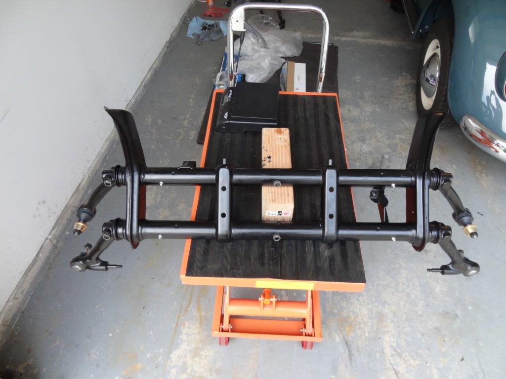
First thing, lets get the rubber body pad placed on the beam. This will be sandwiched between the beam and body, once the beam is installed in the car.
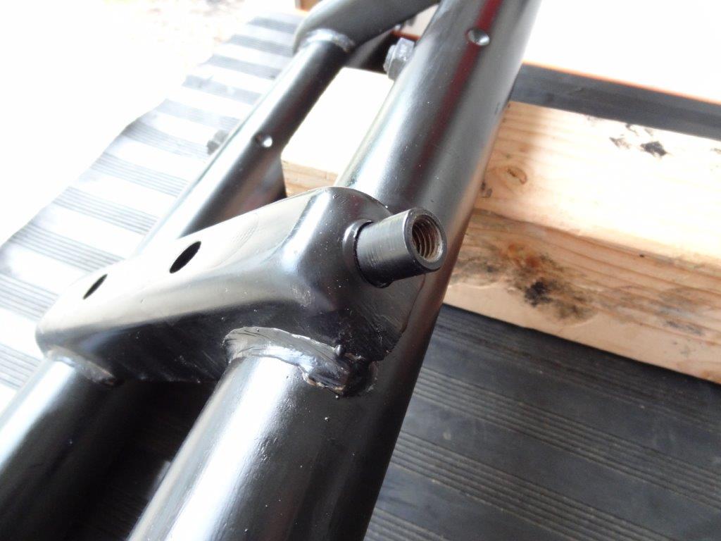
Before:
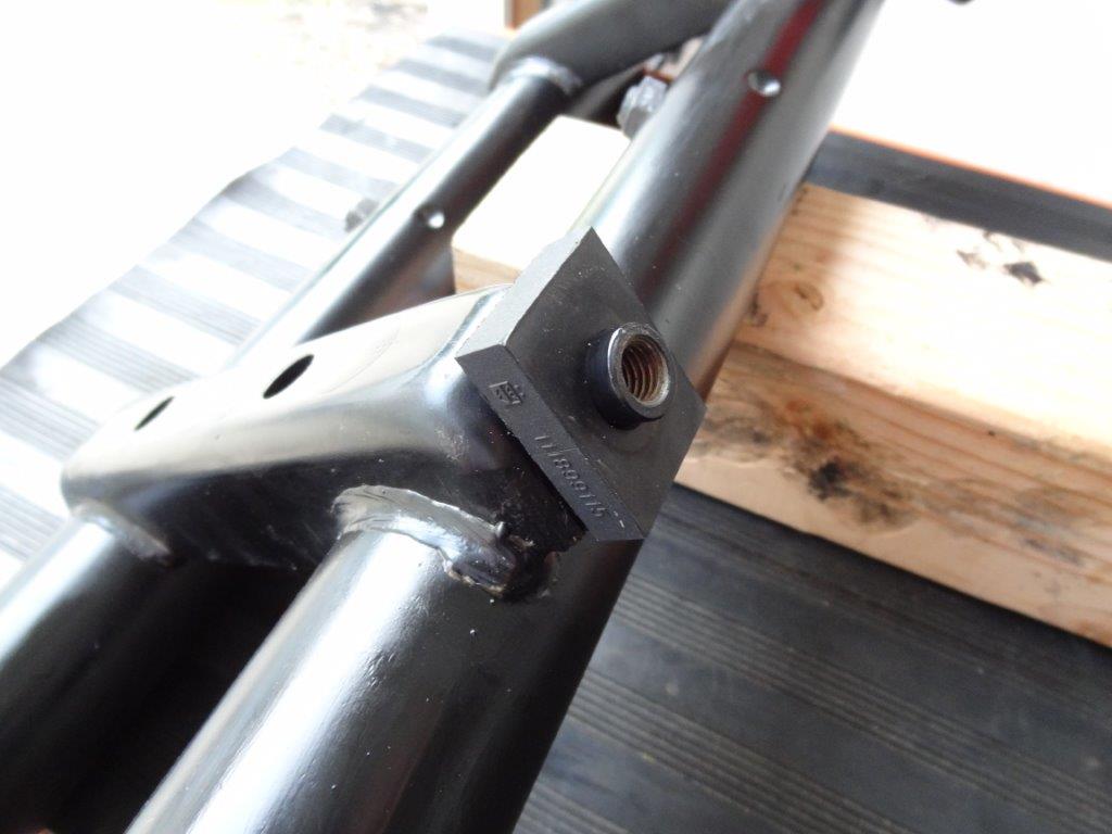
After:
Place the beam into position under the car…
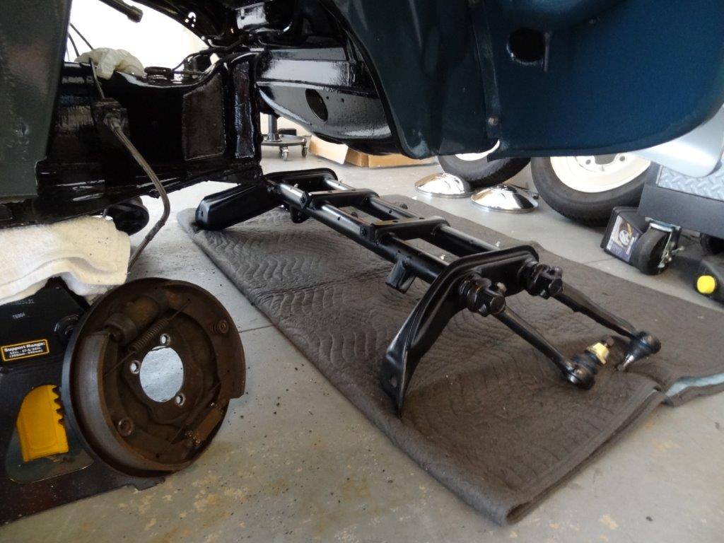
Lift it up into place with a jack and tighten the 4 bolts that hold it to the framehead. Also, tighten the two body bolts that attach from above.
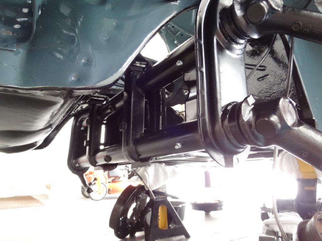
Here it is, installed…
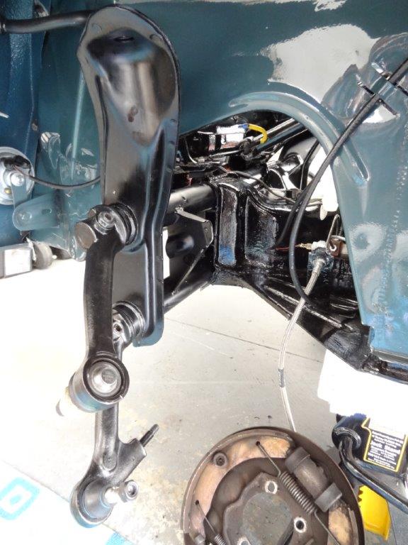
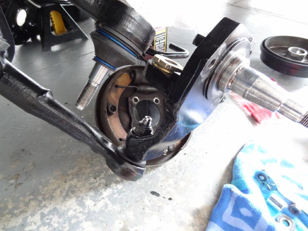
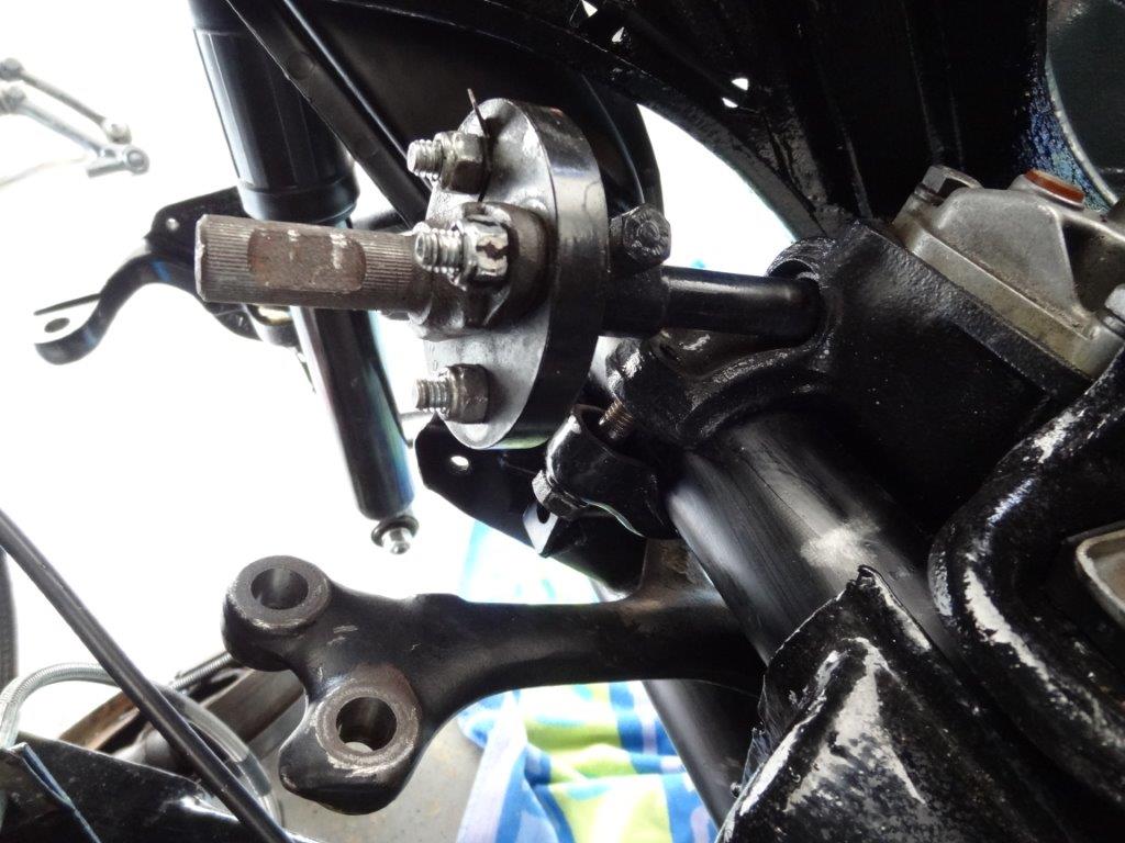
Now that it’s installed, it’s time to install the spindles on to the trailing arms. I’m using the 2.5″ dropped spindles that I removed from the old narrowed beam. I think the 2.5″ drop will still give me a nice look, while maintaining the original VW stock steering/suspension geometry. This first picture shows the spindle installed on the bottom trailing arm. That’s the easy one to install.
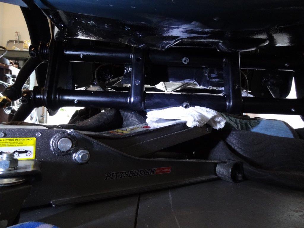
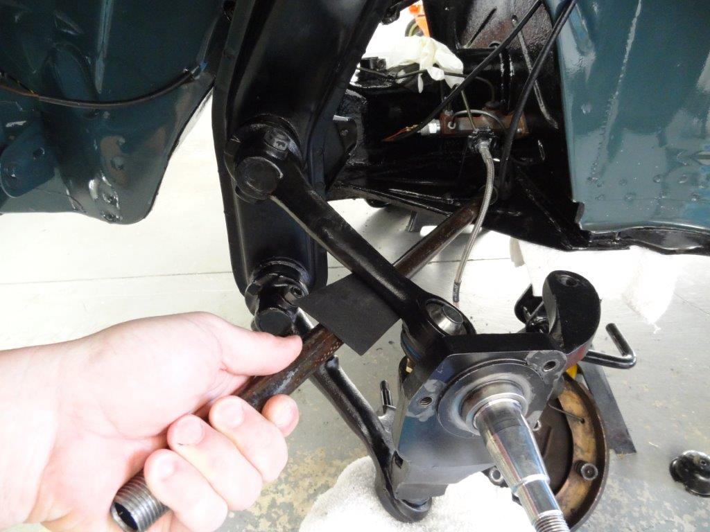
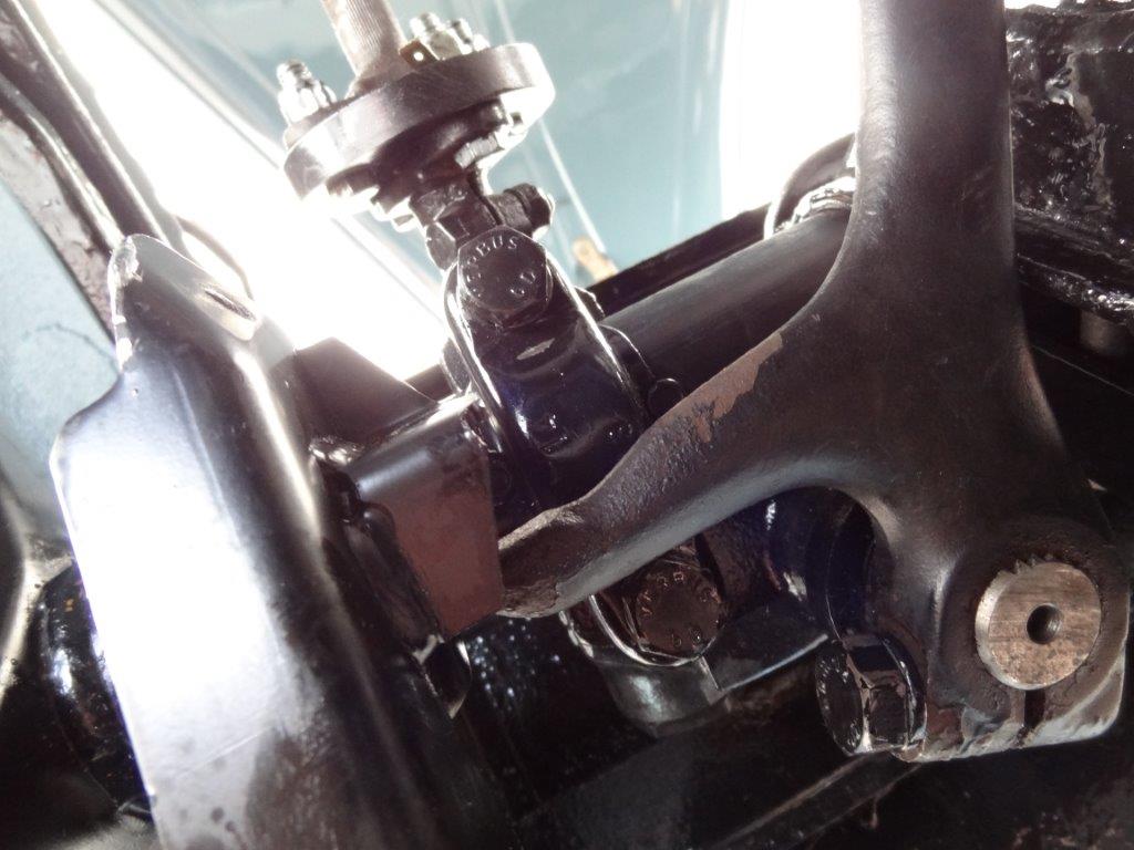
The upper trailing arm is harder to install, and you’ll want to make a tool to help give you some leverage. I used a steel pipe with some lifter channel rubber padding wrapped around the end (don’t want to scratch the nice paint on the chassis). In the picture below, you can see how I used the pipe to help me lift the upper trailing arm into place on the spindle. Also, you can see that I have a jack (under the white towel) that lifted the bottom trailing arm up a bit for a better angle when inserting the upper trailing arm.
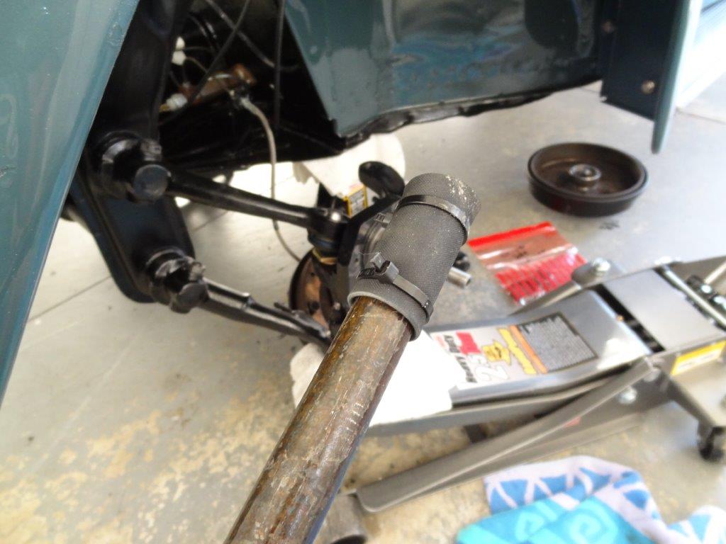
Below shows the lifter channel rubber wrapped around the end of the pipe. You can see in the image above that I also put a layer of the lifter channel rubber between the pipe and the upper trailing arm. Again, it protected the paint and in this case provided some grip.
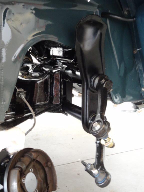
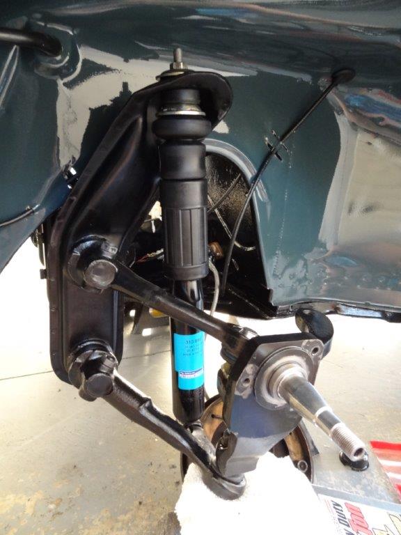
Next, I installed the shock. Looks nice! Nice and clean new parts! 🙂
Next, I installed the steering box, tie rods, and steering damper. I only have pictures of the steering box. Don’t know why/how I forgot to take pictures of the rest. Must have been concentrating on the task at hand! The important thing to know, before hooking up the tie rods, is to make sure you have your steering box spun so that it’s resting in the center position of it’s “throw”. The throw being the distance it travels when you spin it. The Bentley book will show you how to do that. The center of the throw is where it rests when driving straight ahead. Once you find that, then it’s time to hook up the tie-rods to the steering box and the spindles. Make sure your spindles are positioned as close to straight/perpendicular as possible before inserting the tie-rod ends to them. This is important because your steering box is already aligned (if we did it right) for driving straight ahead. I’ll fine tune this later.
Now that the steering box, steering damper, and tie rods are installed, it’s time to get the spindles aligned so the wheels will be tracking straight when driving. Actually, I’m doing this prior to doing a real alignment. I just want them as close to straight as possible, before calculating my toe-in, etc., for the alignment. You’ll see in my next blog post that I eyeballed this pretty evenly (but with too much toe-in).
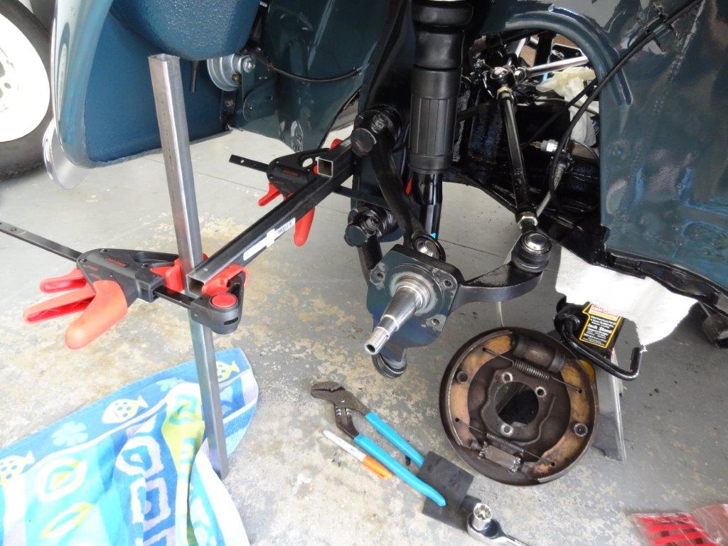
I needed a way to accurately measure the distance from the front of the chassis to each spindle, so I could make sure each spindle center was the same distance from the front of the car. If one spindle was further away than the other, then I’d definitely have some issues and it would make it harder to align. Basically, I needed a starting point prior to doing my alignment. I hooked up these steel square pipes across the front of the beam…
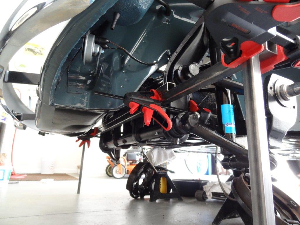
They had to extend past the end of the spindle, so I could take a tape measure and measure straight back to the spindle. You can see I have an additional vertically oriented pipe on the end that I’m measuring from. I didn’t really need to do that, but it was done so the pictures would be more clear. I could have easily measured from the horizontal pipes.
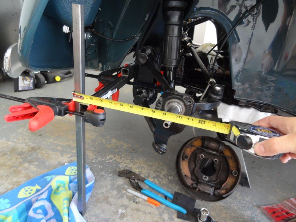
Here are my initial measurements…
Driver side (Measurement: 9-1/8 inches):
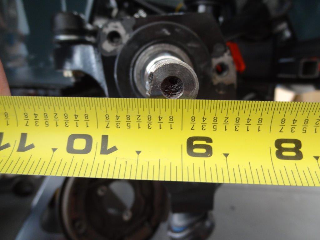
Passenger Side (Measurement: almost 9-3/8 inches):
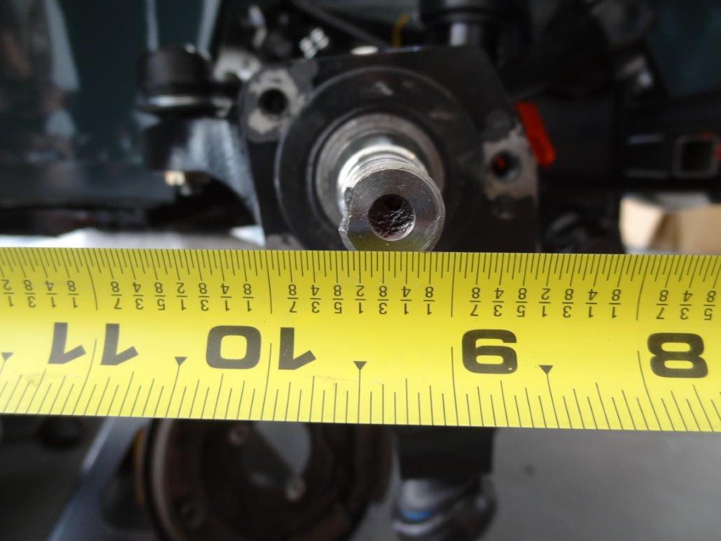
I felt the driver side was most accurate (remember I was eyeballing this). So, I spun the passenger side tie-rod in the appropriate direction a few quarter turns to push the passenger side spindle end forward (toward front of car) about 1/4″ inch. Here’s a picture showing the new measurement.
Once both sides were equal, I tightened down the tie-rod clamps so the tie-rods won’t spin anymore. The tie-rods are threaded on to the tie-rod ends for this very specific reason, to align the car. There is a clamp that you tighten down so they don’t move anymore. Again, sorry, no pictures of that.
So, that’s it. Stay tuned for my next blog post, where I put the drums back on and do a front end alignment.